A Multidisciplinary and Integrated Approach for ESP Design, Operation, and Runlife in a Well Life Cycle
Author- Shahbaz Masih
Introduction
The life cycle of an Electrical Submersible Pump (ESP) in a well consists of design, operation, failure and lessons learned. ESP failures not only cause production interruptions but also add additional workover costs. Premature ESP failures are usually caused by a lack of consideration of the entire ESP system during its design stage or sub-optimal procedures during the installation and operation phases. Some premature ESP failures can be prevented through careful design and operation. However, some ESP’s may require special equipment, analysis of reservoir and fluid properties, and testing to avoid premature failure. Prior studies emphasize the importance of an integrated approach and how to make it more effective by using a multidisciplinary team.
Improved ESP runlife is crucial to minimized workover costs, to maintained production rates, and to meeting production targets.
This article will discuss the importance of different pump design curve parameters considering affinity laws and how a multidisciplinary approach can lead to better pump design. Understanding an integrated multidisciplinary approach by all stakeholders is important for correlation of pump runlife with its design parameters and pump curves. Input by engineering and geoscience teams to determine parameters (e.g. well productivity, scaling tendencies, ESP landing depth) for ESP design and operation is also significant. Finally, ESP operational challenges and possible solutions derived using examples from a multidisciplinary approach will be discussed where reservoir engineering, geoscience, drilling, and site operations, and maintenance teams have input to tackle the problems in the most efficient manner.
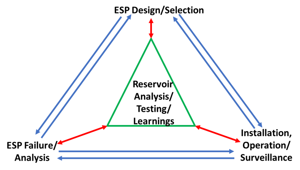
Analysis of types of ESP failures and their root causes have been discussed by many authors and are summarized by Alhanati et al1 and Limanowka et al3. Most ESP failures are attributed to the electrical system that provides energy to the motor and pump because this is often the weakest part of the system. But, the real cause of failure could lie somewhere else. For example, causes of overheating of the motor and pump could include; (a) poor sand control mechanism with resultant inflow of reservoir fines and subsequent plugging. A challenge that may have been pre-empted with a grain size analysis by the geoscience team; or (b) a valve shut off at surface resulting from operational error at site. Therefore, after every ESP failure a root cause analysis should always be conducted. The integrated approach, as discussed by Baillie1, can not only help a proper failure analysis identify the root cause but also help improve pump design and operation, leading to better project economics. Figure 1 shows how integrated learnings from previous pump designs, operations, failure analysis, and input from multidisciplinary teams during the well life cycle, can help boost project economics.
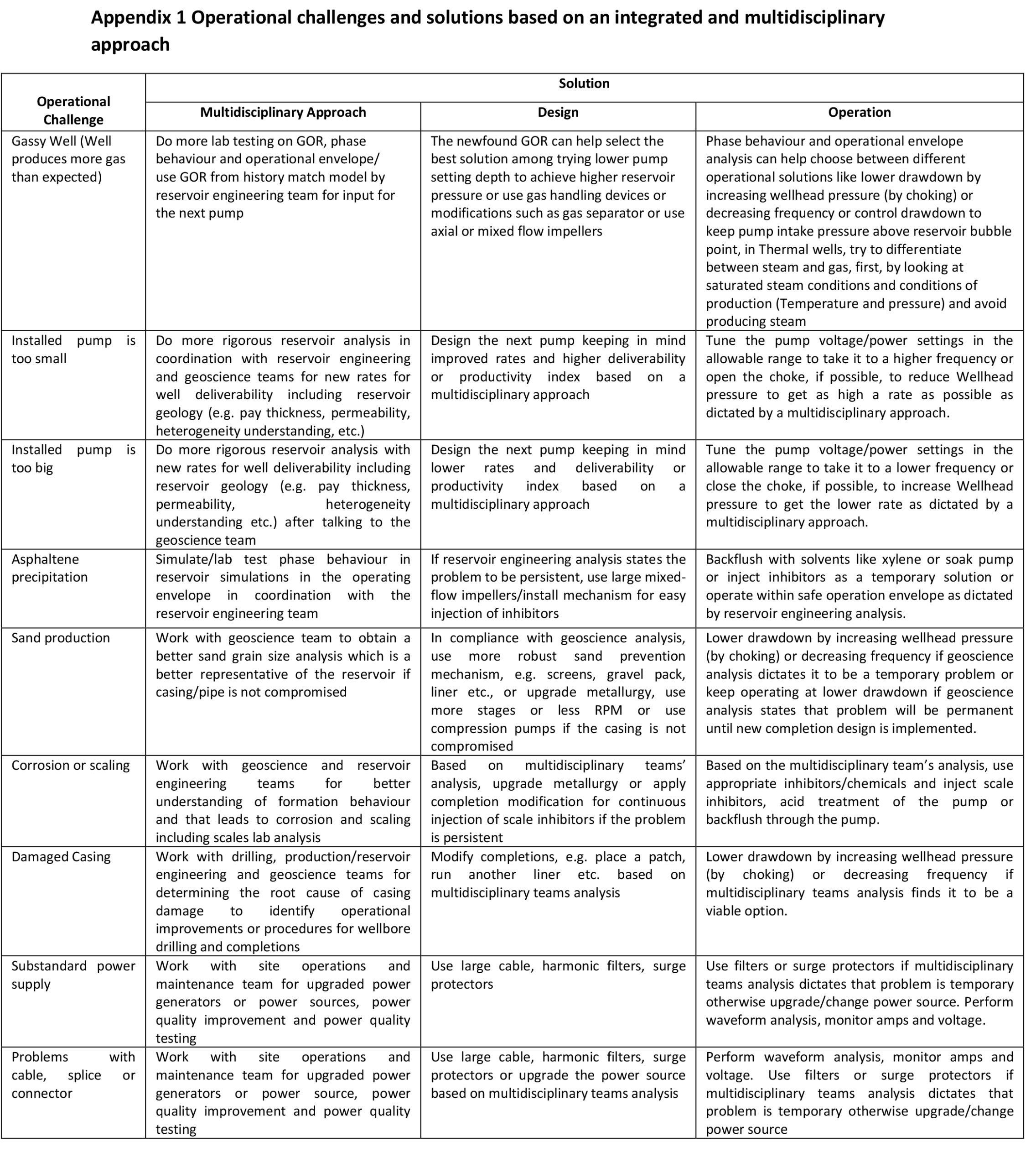
An integrated approach of input from reservoir engineering, geoscience, drilling, site operations, and maintenance team members during pump design, operation and failure analysis can be vital in the follow up ESP design and operation stages. A practical checklist is provided to emphasize the multidisciplinary approach and show how some of the issues and problems that affect the runlife can be solved by taking ESPs as an integrated systems, Appendix 1.
Multidisciplinary and Integrated Approach
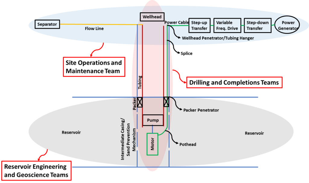
To optimize the runlife of ESP systems, it’s essential to take the ESP, and contributing and surrounding elements as a whole or integrated system. The integrated system approach will help prevent inadvertently overlooking any element that could be the main cause of premature failure. An integrated ESP system is made up of the following major elements, Figure 2.
- Power supply system (generator, transformer, variable frequency drive);
- Three-conductor electric cable that runs through the wellhead down to the motor;
- High-speed three-phase electric motor filled with dielectric oil;
- Seal section which isolates well fluids from the motor and accommodates shaft movement;
- Multistage centrifugal pump consisting of rotating impellers and fixed diffusers;
- Well completions, e.g. tubing, casing, sand prevention mechanism, etc.;
- Reservoir that includes reservoir fluids and reservoir rock (framework, matrix and clays);
- Wellhead; and
- Flow line and separator.
Although, it is difficult to draw the lines between disciplines in an integrated multidisciplinary approach the responsibilities are roughly as follows: elements 1 and 9 fall under site operations and maintenance teams, elements 2, 3, 4, 5, and 6 fall under drilling and completions teams, wellhead (element 8) is designed by completions team and, mainly, operated by site operations team, and element 7 falls under production engineering, reservoir engineering and geoscience teams, as shown in Figure 2.
The purpose of having this division of responsibilities in the multidisciplinary approach is to address each element with the best expertise available. This can lead to a better pump design, operation, failure analysis and learning graph during the life cycle of the well as shown in Figure 1.
Multidisciplinary Approach for the First Pump Design in the Life Cycle of a Well
The initial design of an ESP is performed by determining the average flow rate to be delivered by the pump and total dynamic head (TDH) required. These two parameters primarily depend on the well inflow performance (productivity index and reservoir pressure), and reservoir fluid properties (largely density and viscosity). The ESP system used in the oil industry is modified to include a Variable Speed Drive (VSD). This provides the operational flexibility over a broader range of flow rate, head, and efficiency. An adjustment in operating frequency will alter the motor speed resulting in a change in the pumping speed. Consequently, the developed head, the required brake horsepower, and the produced flow will also be modified. The affinity laws, also called “Pump Laws”, are utilized to express the relationship between variables (head, flow rate, shaft speed and required power), involved in pump design and performance calculation. The following equations express these laws.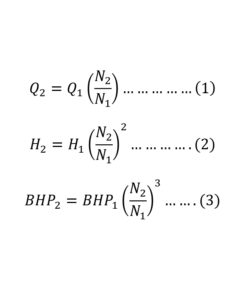
N1 and N2 are pump speeds, Q1 and Q2 are flow rates at speeds N1 and N2. H1 and H2 are the heads developed at speeds N1 and N2. BHP1 and BHP2 are the required brake horsepower at speeds N1 and N2.
These affinity laws are also used to generate pump design curves, as shown in Figure 3 below. While running, all ESP’s develop axial thrust. Axial thrust is an essential factor in establishing the recommended operating range of the centrifugal pump, as shown in Figure 3 below.
The significance of an integrated multidisciplinary approach can be explained by using affinity laws. Erroneous input of inflow parameters such as reservoir pressure, productivity index (dependent upon reservoir characteristics, e.g. permeability), and Gas Oil Ratio (GOR) can lead to erroneous well-flowing pressure (pressure at pump intake) resulting in the inaccurate calculation of desired head. The erroneous GOR also leads to inaccurate flow rate. By using affinity laws equations (Equations 1, 2 and 3), it can be deduced that the incorrect input of inflow parameters not only leads to inaccurate head and brake horsepower but will also affect pump curves, as shown in Figure 3. These inflow parameters are derived from available geological data and reservoir analysis by the geoscience and reservoir engineering team members. Usually, reservoir engineers are consulted for inflow performance parameters on short notice and are not fully aware of the impact of reservoir inflow parameters on the pump design, operation and integrity. This should not be the case.
A smooth and flawless power supply is assumed to be available at the time of the first pump design. The required power is linked to pump rotation speed, which is related to the desired head and, ultimately, flow rate, as shown by affinity law equations above. The parameter of smooth power supply to be provided by the site operations and maintenance team, is equally as important as reservoir inflow performance, for pump design and operation because it is one of the main drivers behind the required head and flow rate. If the expected power is not supplied for a specific pump speed, it will not be able to provide the desired head and flow rate, which in turn compromises not only the pump curve accuracy (Figure 3), but also pump efficiency and ultimately pump integrity.
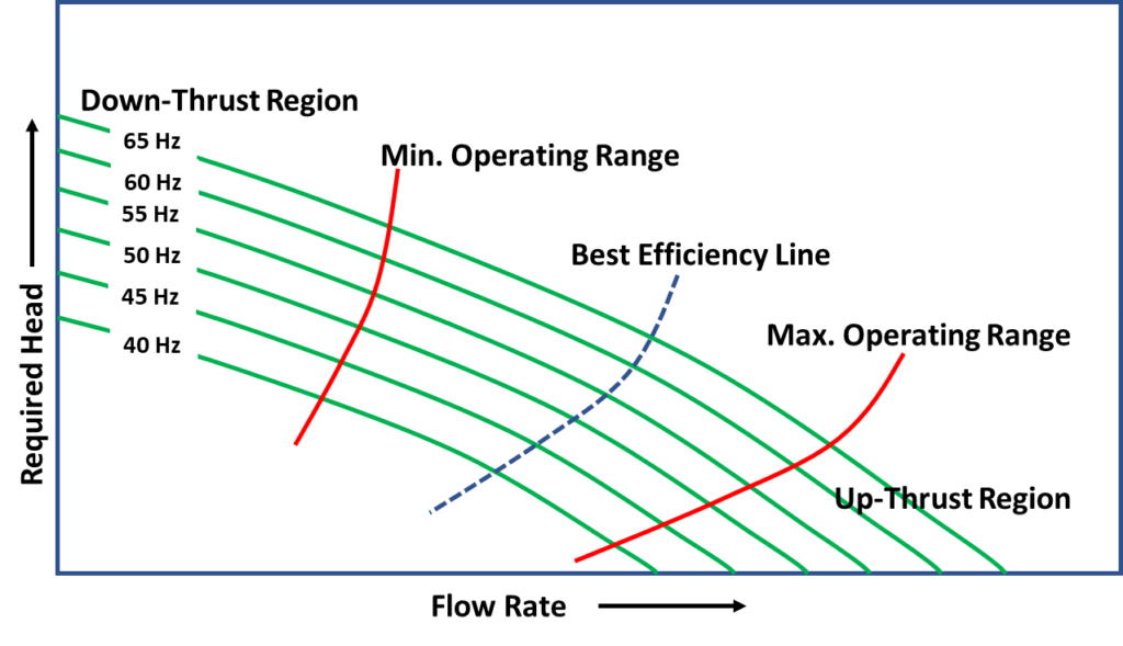
Likewise, well deviation and severe dogleg can put a pump under excessive stress and jeopardize the pump’s integrity. The drilling team needs to be aware of the risk that well deviation and dogleg have on the pump integrity and the subsequent impact on pump design that is required to alleviate that risk. High levels of stress can also impact up-thrust and down-thrust regions in the pump curves, as shown in Figure 3.
An error in the pump curves, as shown in Figure 3, can lead to the wrong calculation regarding the best efficiency point and thrust regions, thereby influencing the pump runlife. Therefore, a multidisciplinary and integrated approach is beneficial to derive the initial pump design input parameters. For example, reservoir inflow performance parameters could be provided by reservoir engineering from analogue history match models which could be different from the parameters provided by laboratory measurements. Additionally, the geoscience team can verify the reservoir characteristics used in the history match model. It can be concluded a multidisciplinary and integrated approach, as shown in Figure 2, can help to improve the pump design and minimize premature pump failure.
Considering that premature ESP failures negatively impact a project’s economics and also hinder production levels, processes need to be developed to facilitate collaboration of multidisciplinary teams on the initial pump design and to optimize pump reliability and operation. Multidisciplinary teams need to understand the importance of their input to ESP design and integrity.
Multidisciplinary and Integrated Approach for ESP Operational Challenges
The first ESP design for a well requires a lot of testing and input from multidisciplinary teams. Even after using the best available data sets, there may still be surprises due to lack of understanding of the spatial variance in key reservoir parameters, the electrical power supply system and the completions, all of which can lead to ESP operational issues. Resolving these issues requires an integrated and multidisciplinary team approach, as shown in Figure 2. The integrated approach helps determine the root cause of the pump issues and a multidisciplinary approach helps achieve a better solution to optimize ESP operation and enhance pump runlife. Some of these challenges along with their possible solutions by using an integrated and multidisciplinary approach for pump design and operation are outlined in Appendix 1 below. Though all potential challenges and solutions are not covered, Appendix 1 highlights the philosophy behind an integrated and multidisciplinary approach to derive solutions to operational challenges. The following discussion covers the methodology with a few examples.
Discussion
Example 1: If a well is producing more gas than the original Gas Oil Ratio (GOR) value used for the initial pump design, a more detailed and comprehensive analysis of GOR is required to improve subsequent pump designs. One solution would be additional lab testing of representative reservoir fluid samples, study of phase behaviour and to select a GOR according to the operational envelope. But, due to changing operational conditions, especially in thermal operations, selecting a representative GOR can be a challenge. The history match of the available production data might provide insight into this problem. Therefore, the reservoir engineering team should be consulted. The excessive GOR can not only hamper production but also affect pump efficiency and its integrity during operation. The updated GOR number derived from lab testing and history match can be used to find the best fit solution (gas handling devices or mixed flow impellers, etc.) for design of the next pump. If both the lab test and history match results indicate a higher GOR than the one used in design of the previous pump, the pump operational philosophy can be adjusted to run the pump at optimum rates in order to obtain the ESP runlife that justifies the well or project economics.
Example 2: Another ESP operational challenge often faced by production engineers is that the installed pump is too big. The pump must be operated at very low rates (in the down thrust region in some cases, as shown in Figure 3), which can lead to premature failure. This is mainly due to a lack of information for reservoir characterization (permeability, etc.) and spatial delineation for geoscience and reservoir engineering teams to determine inflow performance. The operation of an ESP at such low rates may require the re-evaluation of reservoir parameters by the geoscience team and the productivity index or well deliverability by the reservoir engineering team. The new productivity index and inflow performance will not only improve the design of the next ESP in the pump life cycle but also may help the operation with the current ESP. Based on new inflow performance, the current running pump can be tuned for lower frequency, lower rate, by changing power supply settings in the transfer. The lower range frequency settings can help avoid pumping off or a low flow condition and optimize the pump function.
Example 3: The final example is an issue with electrical connections, e.g. splice, pothead, etc. An integrated and multidisciplinary approach can lead to an appropriate solution for this challenge because the issue might lie in the quality of power supply. Therefore, the field operations and maintenance team must be involved. The answer might also lie in upgrading the power source, i.e. generator, harmonic filters, or power surge protectors. Also, the power supply might need continuous testing and monitoring by performing waveform analysis for voltage or amps. The field operations and maintenance team best understand the power supply source, protective equipment and quality testing procedures. Their involvement will help smooth the operation of an ESP and avoid premature ESP failure due to connection and power supply problems.
Conclusions
Some premature ESP failures can be avoided or minimized by taking a multidisciplinary and integrated approach to the design and operation phases of the ESP system. The effectiveness of an integrated approach depends upon a holistic multidisciplinary approach requiring contribution from completions, production and reservoir engineering, geoscience, drilling and site operations and maintenance teams. Furthermore, processes need to be developed across organizations for the effective communication, training and learning of these multidisciplinary teams to optimize ESP design and operation.
Acknowledgement
The important technical input provided by Mark Savage P.L. Geo., towards writing this article is greatly appreciated.
References
- Alhanati, F. J. S, Solanki, S. C., and Zahacy, T. A., “ESP Failures: Can we Talk the Same Language” SPE Electrical Submersible Pump Workshop, Houston, Texas, 2001.
- Baillie, A., “Optimising ESP Runlife – A Practical Checklist”, 7th European ESP Round Table, Aberdeen, 2002
- Limanowka, A. W., Voytechek, M., and Degen, S.D. “Root Cause Failure Analysis of Electrical Submersible Pumping Systems” SPE Electrical Submersible Pump Workshop, Houston, Texas, 1999.
- https://production-technology.org/
About the Author
 Shahbaz Masih is APEGA registered professional engineer with M.Sc. from University of Regina (Canada) and B.Sc. from UET Lahore (Pakistan), both in Petroleum Engineering. He has worked in the Canadian oil industry for more than ten years with Cenovus Energy, Statoil Canada Ltd., and Sunshine Oilsands Ltd. Main highlights of his work experience include reservoir simulation for SAGD, CSS and solvent assisted processes for process optimization and project development, optimization of SAGD operation holistically and its wells completions, reservoir management by using multidisciplinary approach, ESP’s design, operation and failure analysis, production management and an NSERC research project focused on porous media flow in SAGD.